Create an entity relationship diagram illustrating the existing data tables. Entity Relationship Diagram Examples 2022-12-27

Create an entity relationship diagram illustrating the existing data tables Rating: 5,4/10 530 reviews

An Entity Relationship Diagram (ERD) is a visual representation of the relationships between entities in a database. It is used to model and design the structure of a database by identifying the entities and the relationships between them. In this essay, we will create an ERD illustrating the existing data tables of a hypothetical database.

First, let's define the entities that will be included in the ERD. An entity is a person, place, or thing that is relevant to the database. For example, in a database for a school, the entities might include students, teachers, classes, and subjects.

Next, we need to determine the attributes of each entity. An attribute is a characteristic or property of an entity. For example, a student entity might have attributes such as first name, last name, and student ID.

Once we have defined the entities and their attributes, we can begin creating the ERD. The ERD consists of boxes representing the entities and lines connecting the boxes representing the relationships between the entities.

For our hypothetical database, let's consider a database for a small online store. The entities in this database might include customers, orders, products, and payment methods. The attributes for the customer entity might include customer ID, first name, last name, email address, and mailing address. The attributes for the order entity might include order ID, customer ID, product ID, quantity, and order date. The attributes for the product entity might include product ID, name, description, price, and category. The attributes for the payment method entity might include payment method ID, customer ID, and payment details.

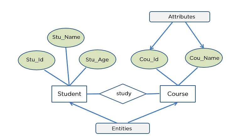
Using these entities and attributes, we can create the following ERD:

[Insert ERD diagram here]

In this ERD, the boxes represent the entities and the lines connecting the boxes represent the relationships between the entities. For example, the line connecting the customer and order entities indicates that each order is placed by a single customer. The line connecting the order and product entities indicates that each order consists of one or more products. The line connecting the customer and payment method entities indicates that each customer can have one or more payment methods on file.

Creating an ERD is an important step in the process of designing a database. It helps to visualize the relationships between the entities and ensure that the database is properly structured to meet the needs of the business or organization. By creating an ERD, we can effectively plan and design a database that is efficient, accurate, and easy to use.

Entity Relationship Diagram (ERD)

create an entity relationship diagram illustrating the existing data tables

In this section, we will give you some ERD tips. This allows for simplified editing using These instructions may work for SQL Developer 3. . It could be customer order. This list includes all entities tables and views in the repository and highlights the ones linked to the ones already on the diagram and the ones assigned to this particular subject area subject area groups tables and other objects. They are not scary. You can add tables later on.

Next

How to create ER diagram for existing SQL Server database with SSMS

create an entity relationship diagram illustrating the existing data tables

Logical data model example Physical data model Physical ERD represents the actual design blueprint of a relational database. Basic flowcharts are used to represent a simple process algorithm. . This table holds information about customer orders. When an ERD is drawn for physical database development, it is important to ensure the use of types that are supported by the target RDBMS. In a typical ER design, you can find symbols such as rounded rectangles and connectors with different styles of their ends that depict the entities, their attributes, and inter-relationships. LucidChart has plenty of collaboration options so you can work on the diagram with your teammates collectively with features like sticky notes, comments, and mentions.

Next

Entity Relationship Diagram Examples

create an entity relationship diagram illustrating the existing data tables

Unfortunately, it takes a lot of time to write a business plan and to find a great location, although some know how to create a restaurant floor plan in minutes or how to plan budget effortlessly. Entity Relationship Diagram Examples. An ERD is a data model that describes how entities or concepts relate to one another. After including the SalesOrder table and the SalesOrderItems tables from your Best Run Bikes dataset into the model, they must now be associated to each other. For example, Student Name can be divided as Student First Name, Student Middle Name, and Student Last Name. A weak entity is one that depends on a strong entity for existence.

Next

Entity

create an entity relationship diagram illustrating the existing data tables

I often start by drawing one in my notebook. Visual Paradigm provides you with not only an ERD tool but also a set of visual modeling features that helps you draw faster and easier. You will get the sales data of Best Run Bikes and it is your mission to use the features of SAP Data Warehouse Cloud to help the bike suppliers make the best possible business decisions. While ER models are mostly developed for designing relational databases in terms of concept visualization and in terms of physical database design, there are still other situations when ER diagrams can help. An ERD will also often visualize the attributes of these entities. You will learn things like what is ERD, why ERD, ERD notations, how to draw ERD, etc.

Next

Microsoft Tools that Help: How to Create an Entity Relationship Diagram

create an entity relationship diagram illustrating the existing data tables

For example, an enrolment of a student may be a weak entity, as an enrolment cannot exist without a student. Thank you for taking the initiative to create one of these ERDs yourself. Double Ellipses: These represent multi-valued attributes. A logical ER model is developed to enrich a conceptual model by defining explicitly the columns in each entity and introducing operational and transactional entities. With an ERD, Chen could provide a unified framework for database modeling.


Next

What is Entity Relationship Diagram (ERD)?

create an entity relationship diagram illustrating the existing data tables

You can draw ERD as a complement to DFD by representing the structure of information that flows within a system, or, on the contrary, to draw DFD in complementing an ERD by showing how the data will be utilized by the system in runtime. Making entity-relationship diagram based on the Chen ERD notation is simple now having ConceptDraw DIAGRAM and you can check it yourself once you download and use it. Entity-relationship models can also help in Business process re-engineering and modeling new databases. Don't worry if there are orphan entities. Adding relation labels SSMS enables you to add labels to the relationships.

Next

ER Model: What is an Entity Relationship Diagram

create an entity relationship diagram illustrating the existing data tables

If you crate diagram for the first time you may get the following message: SSMS requires some system procedures and a table that are not created with the database. Exporting diagram Management Studio enables you to export diagram to image. You can decide on specific columns, tables, or the entire diagram. This will always be visible and export with your diagram. Its existence is not dependent on any other entity. Or are you developing an ER model ready for database creation? The three common cardinal relationships are one-to-one, one-to-many, and many-to-many.

Next

How to generate an entity

create an entity relationship diagram illustrating the existing data tables

Each of these levels has a different level of detail and are used for a different purpose. A physical data model elaborates on the logical data model by assigning each column with type, length, nullable, etc. When you add all required tables click Close button. Database model is a graphic representation need at the beginning of project development. Student , tangible business objects e. An ERD represents entities and their attributes and relations, whereas a relational or physical model represents tables, columns, and foreign keys.

Next

Create an Entity Relationship Model in SAP Data Warehouse Cloud

create an entity relationship diagram illustrating the existing data tables

Look at two entities, are they related? By the way, you have this sample here. For example, an employee's social security number might be the employee's key attribute. Hence, ER diagrams are used for analyzing and designing business information systems. You're either designing a new schema or you need to document your existing structure. They can also be created on an existing system to help the team understand how the system works and to find and resolve any issues. Using a diamond inscribed in a rectangle speaks of an associative entry. You can export your database structure as a CSV file This will be the most accurate portrait of your database and will require no drawing on your part.

Next