Er model diagram examples. Entity Relationship Diagram 2023-01-04

Er model diagram examples Rating: 7,2/10 1961 reviews

An Entity-Relationship (ER) diagram is a graphical representation of the relationships between entities in a database. These diagrams are used to design and model databases, as well as to communicate the structure of a database to stakeholders. In this essay, we will look at some examples of ER diagrams and discuss their key components and uses.

One common example of an ER diagram is a diagram that represents a simple customer database. In this case, the entities might include customers, orders, and products. The relationships between these entities might include:

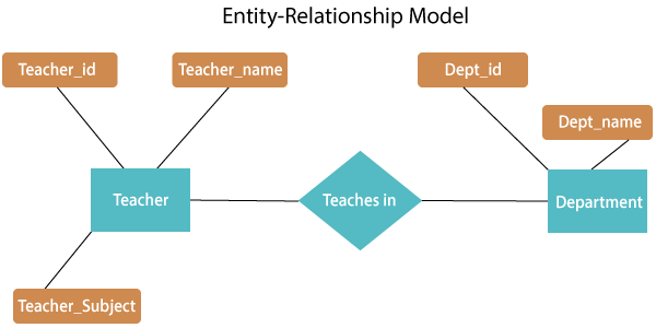
In this example, the customer entity would be represented by a rectangle, the order entity by a diamond, and the product entity by an oval. The relationships between these entities would be represented by lines connecting the shapes, with the relationship name written along the line.

Another example of an ER diagram is one that represents a university database. In this case, the entities might include students, courses, professors, and classrooms. The relationships between these entities might include:

In this example, the student entity would be represented by a rectangle, the course entity by an oval, the professor entity by a triangle, and the classroom entity by a rhombus. The relationships between these entities would be represented by lines connecting the shapes, with the relationship name written along the line.

ER diagrams can also include attributes, which are characteristics or properties of an entity. For example, in a customer database, a customer entity might have attributes such as name, address, and phone number. These attributes would be represented by oval shapes connected to the entity rectangle by lines.

ER diagrams are useful for database design because they provide a clear and visual representation of the relationships between entities and the attributes that make up those entities. They are also useful for communicating the structure of a database to stakeholders, such as developers or business analysts, who may not have a technical background in database design.

In conclusion, ER diagrams are a valuable tool for designing and modeling databases. By representing entities, relationships, and attributes visually, they provide a clear and concise way to understand the structure of a database.

Entity Relationship Diagram Examples

er model diagram examples

An oval showcases the composite attribute, and the composite attribute oval is further connected with other ovals. In the example below, both the student and the course are entities, and study is the relationship between them. Other relationships such as M: N can also be observed. The fourth step is identifying entity attributes. Using set, it can be represented as, Every student in Student Entity set is participating in a relationship but there exists a course C4 that is not taking part in the relationship.


Next

ER Model: Entity Relationship Diagram (ERD) with Examples

er model diagram examples

However, ER Diagram includes many specialized symbols, and its meanings make this model unique. One-to-Many Association With Mandatory Relationship Many-to-Many This type of cardinality occurs when multiple instances of one entity can relate with more than one instance of another set of entities. The user can check out the variety of ERD examples, making it easier for them to create their ER diagram. It is used for identifying different system elements and how they interact with each other. This sample shows the work of the Financial Trade sphere and can be used by trading companies, commercial organizations, traders, different exchanges. Composite Attribute An attribute that is composed of several other attributes is known as a composite attribute. Example: One student can enroll in any number of course zero or many or one course can be enrolled by any zero or many number of students.

Next

Free Editable ER Diagram Examples

er model diagram examples

This is called total participation. This relationship has two roles such as employee and manager with the employee entity. Composite attribute It is possible to break down composite attribute. Step 5 Create the ERD Diagram A more modern representation of Entity Relationship Diagram Example Here are some best practice or example for Developing Effective ER Diagrams. So, EMPLOYEES is a strong entity and DEPENDANT is a weak entity. This diagram consists of actors, use cases and relationships between them.

Next

Entity Relationship Diagram Examples & Templates

er model diagram examples

You can also conduct interviews with various stakeholders to identify entities. So it is many to many relationships. Here are some examples for the users who can follow them follow reference while working on their ER diagram. The relationship between one strong and a weak entity set shown by using the double diamond symbol. Such attributes are called single-valued attributes. For example, A person's age changes over time and can be derived from another attribute like Date of birth. Multivalued Attribute Some attributes can possess over one value, those attributes are called multivalued attributes.

Next

A Guide to the Entity Relationship Diagram (ERD)

er model diagram examples

Symbols and notations When creating an ERD, it can be simple to create boxes and lines between them. To do so, an entity-relationship diagram highlights entities, attributes, and relationships through predefined symbols for effective visualization of the architecture. One-to-One Association With Mandatory Relationship One-to-One Association With Optional Relationship One-to-Many A one-to-many relationship occurs when one instance of an entity can interact with multiple instances of another entity. It is commonly known as an ER Diagram. Other systems can be more complex with a more significant number of entities such as staff etc. For example, Scientist can invent many inventions, but the invention is done by the only specific scientist. ConceptDraw DIAGRAM on Mac OS X supplied with Entity-Relationship Diagram ERD Solution from the Software Development Area for ConceptDraw Solution Park is the best ERD tool! Weak entity is dependent on strong entity to ensure the existence of weak entity.

Next

ER Diagrams in DBMS: Entity Relationship Diagram Model

er model diagram examples

An Entity Relationship Diagram ERD is a type of diagram that lets you see how different entities e. Besides, we can also find other relationships between customers and admin, products and admin, etc. Examples: A Pharmacy Management system can have entities such as drugs, cash, injections, bills etc. So the relationship will be many to many. Relationship is nothing but an association among two or more entities. With marked-up relationships among data sets, an ER diagram is perfect for process modeling and system debugging. While in production, an ER diagram acts as a reference to improve database throughput, debug errors, and redesign architecture.

Next

ER (Entity Relationship) Diagram Model in DBMS Examples

er model diagram examples

In other words, ER diagrams help to explain the logical structure of databases. The diamond symbol represents it. They can relate the students' details like name, years, courses, and then details of the courses and course teacher. It is a high-level data model diagram which defines the conceptual view of the database. The third section is for the teams. An entity can be any person, any object, any place, or event relevant to a given database system. Example 10: Examination Schedule ER Diagram Source: The ERDs can also help institutes to organize the exam schedule perfectly.


Next

Entity Relationship Diagram

er model diagram examples

I often start by drawing one in my notebook. There are some sub-elements which are based on main elements in ERD Diagram. The number of instances of any entity associated with any other relation is known as Cardinality of the Entity. Entity-relationship diagrams ERDs are used to visualize data and relationships among the entities of a system. ER diagrams are created based on three basic concepts: entities, attributes and relationships. Specifically, the cardinality indicates the number of times one entity in a table can relate with the instances of another entity.


Next

Explaining an ER Diagram, With Steps and Use Cases

er model diagram examples

It helps in providing a framework for creating and manipulating databases. It showcases an entity as a rectangle in an ER diagram. This can help you translate a description of what you need to diagram into an actual diagram. A weak entity is represented by a double rectangle. For example, one class is consisting of multiple students.

Next