Transient analysis in Multisim is a type of simulation that allows engineers and designers to analyze the behavior of an electronic circuit over a specific period of time. This analysis is useful for understanding how the circuit will respond to various stimuli, such as changes in input signals or changes in environmental conditions.
One of the main benefits of transient analysis in Multisim is that it can provide a more accurate representation of a circuit's behavior compared to other types of simulation, such as DC or AC analysis. This is because transient analysis takes into account the time-varying nature of signals and the inherent delays that occur within a circuit.
To perform a transient analysis in Multisim, the user must first set up the circuit to be simulated and define the time frame over which the analysis will be performed. This can be done by specifying the simulation time, the time step, and the type of analysis to be performed (such as DC or AC). The user can then apply various stimuli to the circuit, such as input signals or voltage sources, and analyze the response of the circuit over time.
One of the key features of transient analysis in Multisim is the ability to create and analyze different types of waveforms, such as sinusoidal or square waves. This allows the user to study the behavior of the circuit under different types of input signals and understand how the circuit will respond to different types of stimuli.
Overall, transient analysis in Multisim is a powerful tool that allows engineers and designers to accurately predict the behavior of electronic circuits over time. By taking into account the time-varying nature of signals and the inherent delays within a circuit, transient analysis provides a more accurate representation of a circuit's behavior compared to other types of simulation. This makes it an essential tool for understanding and optimizing the performance of electronic circuits.
Run a Transient Analysis on the Multisim circuit in Fig. 7
Are the above mentioned parameters the ones you advised? But a normal Multisim behavior. If that is the case, multiplying those values by 1,000,000 is supposed to give the simulation parameters that you need e. Thanks for your kind reply! My aim is just to plot the current, which I expect to remain visible not vanish up to a time of say 5 seconds. Diego H National Instruments Thanks very much Diego! As you can see, this is the typical underdamped response of a series RLC circuit. Start time TSTART Start time of Transient Analysis.
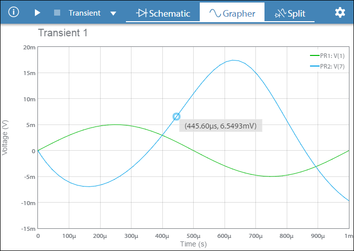
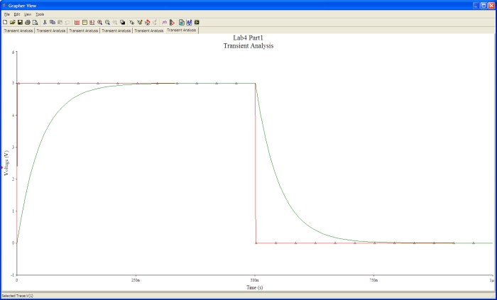
Finally, the results, voltage versus time, are presented in the Grapher View. I found that my original NI Multisim 14 schematic bombed out at about 100 millisecond. I'm trying to run a transient analysis on a circuit at various node. This is from the sample circuits inside Multisim. But the issue was still there. This would then present the output as current vs time on the grapher display.
. You kindly provided a weblink that relates to 'simulation error'. You can just use the largest allowable time step of 1e-5 s. Select a Start Time of 2. The default settings are appropriate for normal use, providing the transient response of the selected output variables starting at time 0 seconds and stopping after 1 ms.
Current has to be measured in series with the wire or component. How do I add the currents to the list? With these limitations alone you may still be able to properly simulate the circuit. Not convinced that the result is correct but that is not the issue. It is a transient analysis, but I'm expecting that the 50 Hertz current should not just disappear at 100 millisecond. I'll make sure to use the general Multisim resistors from now on.
1 Configuring a Transient Analysis in blog.sigma-systems.com
I just want one data point per second because the discharge is rather slow, however the simulation keeps occurring in micro seconds steps. These analyses range from the basic to sophisticated. The Transient window shows the units for TSTOP, TSTEP, etc are in seconds, your idea that maybe behind the scenes the time unit were micro seconds was clever but it seems that is not the case. If this virtual burn-out is really what happened, then Multisim is very impressive - although, a pop-up message to warn about this would have sorted it out quickly. Maximum time step the simulation can handle. Notice that the values for the parameters don't have units.
. The analysis starts from initial conditions as set in the Transient Analysis window. Step responses of the RLC circuit. I would say this is why in the default options there is no option for Current to measurement until you add the probes. Estimate maximum time step based on netlist TMAX This becomes enabled when the Maximum timestep TMAX checkbox is selected. Finally, the results, voltage versus time, are presented in the Grapher View. Please see attached: Diego H National Instruments.
Also your time step should be considerably smaller than the period of the oscillation ~225 ns. For Initial time step: Time step must be greater than 1e-12 and less than or equal to the maximum time step. . Select a Start Time of 2. You can tolerate the slowing down of simulation if you are eager to get the result.
For each analysis you need to set settings that will inform Multisim exactly what to analyze, and how. Hello KennyL It seems you used a 5s for Maximum time. In this example you executed the simulation three times in order to get the step responses of the RLC circuit, however, you can also use. Multisim simplifies the procedure for an advanced analysis by providing a configuration window. Lynn DC gain is not relevent to the stability of an opamp circuit.
At least the result is within the range expected and the circuit is oscillating. I made some progress here. That is, the simulated waveform I L1 dropped permanently to zero at 1. I stated above that this is "supposed" to get you to the correct parameters, this is because of the limitations on Maximum time step and Initial time step. .