Water level alarm circuit project. 5 Simple Water Level Controller Circuits 2022-12-31

Water level alarm circuit project Rating: 8,3/10 587 reviews

An "about me" speech is a short, personal introduction that allows you to share information about yourself with your audience. It can be used in a variety of contexts, such as at a job interview, during a presentation, or as a way to introduce yourself to a group of new people.

There are a few key elements to include in an "about me" speech. First, you should start by introducing yourself and giving your name. You can also provide a brief overview of your background, including where you grew up, your education, and any notable achievements or experiences.

Next, it's important to highlight your interests and hobbies. This can help to give your audience a sense of who you are as a person and what you enjoy doing in your free time. It's also a good idea to mention any skills or expertise you have, as this can help to show your audience what you are capable of and how you might be able to contribute to a group or project.

Finally, you should conclude your "about me" speech by sharing your goals and aspirations. This can be a great way to motivate and inspire your audience, as well as to give them a sense of what you are working towards.

Here's an example of an "about me" speech:

Hi, my name is [Name] and I'm from [City/State]. I grew up in a small town and always had a love for learning. I received my bachelor's degree in [Field of Study] from [University] and have since worked in a variety of roles related to my field of study. In my free time, I enjoy hiking, reading, and playing the piano. I'm also an avid fan of science fiction and fantasy novels.

One of my biggest passions is using my skills and expertise to make a positive impact in the world. I believe that education is the key to unlocking our full potential and I'm always looking for new ways to contribute to my community. My goal is to eventually become a teacher and inspire the next generation of leaders and innovators.

Thank you for taking the time to get to know me. I'm excited to be a part of this group and hope to contribute in any way that I can.
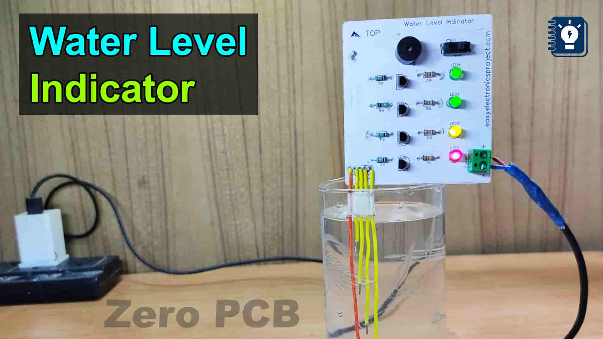
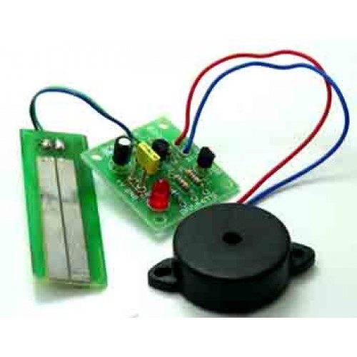
Water Level Indicator Alarm

water level alarm circuit project

During the off period the BC557 Collector voltage goes to zero but then rises to about 1 volt and thus the output 3 of IC4017 goes to 12 Volts turning the output relay on again. We have posted a wide variety of water level sensorsmall electronic projects in project for school studentsto detect the water levels inside the water tank or any water reservoir. However, these display levels can be increased or decreased depending upon the level resolution required. This makes the ULN 2003 IC suitable for switching inductive loads. For the circuit to cycle the latch circuit needs to switch ON OFF in response to the output switching of the IC.


Next

How to Make a Simple Water Tank Overflow Alarm : 4 Steps (with Pictures)

water level alarm circuit project

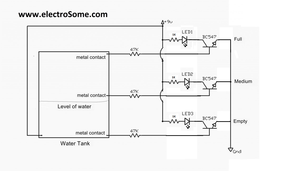
Seetharaman, I am an electronics hobbyist novice and I lack theory. Can you help me telling me how to deal with the circuit running reversing the relay? Do i need to change resistor value or increase the 6V AC. Sir whwen I connected the MOV at 220V side the voltage reduces to 30-40V, and thus circuit does not work…………. This is the circuit diagram of a simple corrosion free water level indicator for home and industries. I have a very similar necessity. Connect three 1K resistors to the pin 15, 13 and 10 of ULN 2003 IC, as shown in the circuit diagram. I reduced the value of R1 to 330 ohms as suggested by Sri Seetharaman Oct.

Next

Simple Water Level Indicator Circuits (with Images)

water level alarm circuit project

With this simple project, you can monitor the water level in the tank. Anticipating your earliest reply to my E mail. I need it to run at the NC position because I have a Preassure sensor to activate the pump and I want to disable the system when no water is at the bottom level sensor opening it. The advantage of the water tank overflow liquid level sensor alarm circuitis that itsaves waterfrom accidentaloverflow. ??? The yellow light will glow.

Next

Water Level Alarm

water level alarm circuit project

So to the return line I put a bridge circuit using 1N4001 and converted it to DC and gave it to a LED with resistance in series as load. Does the circuit work by using electrolyte capacitors 0. The circuit in the video is tested and confirmed so I would recommend this circuit. I'm using every thing as you told. I have a problem. The ends of probes of the water tank level indicator are connected to corresponding points in the circuit as shown in circuit diagram.

Next

Simple Water Level Indicator with Alarm (3 Tested Circuits)

water level alarm circuit project

This float sensor is used to detect the level of the water inside a water tank. When the both sensors are powered then the relay become open instead of closed. Therefore when you switch on your unit if you see only one Red LED lighting up then you know that the is no water present in the tank and therefore you should make you water pump on. I converted the voltage to D. .

Next

Water Tank Overflow Liquid Level Sensor Alarm Circuit

water level alarm circuit project

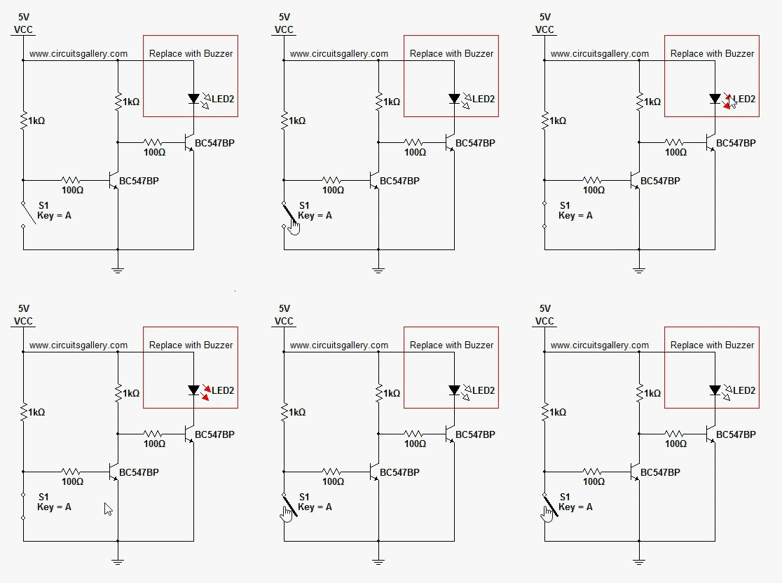
. With your new circuit i can clearly see where to incorporate the two transistors to control the relay for switching power to pump and heater. This turn ON the white LED and the buzzer connected to the transistor Q3. It also means that the inputs of the relevant The outputs from N2 and N4 also remain at low logic, keeping the relay and motor switched OFF. For the common line you can use a naked wire running through the nut bolts bare touching each other. Thecircuitschematic forthe water tank overflow alarmis shown below. Here, we have used BC 547 as a Switch.

Next

Water Level Sensor Circuit

water level alarm circuit project

The power supply is a plug in 120 volt to 6 volt ac step down transformer with an output of 600Ma. Water Level Indicator and Alarm Using ULN2003 One can implement this circuit using simple ULN2003 IC. I would appreciate the full details for the modifications required with values and how they are connected. This is rectified using a bridge rectifier and given to the LED. The Buzzer Part Here you can add any of the normal buzzers that are readily available in the market and if it is not then you can make yourself with a simple 555 IC.

Next

Simple Water Level Indicator Alarm Circuit Diagram

water level alarm circuit project

This immediately switches ON the BC547 attached with pin 4 of the IC, and it grounds the pin 4 with the negative line. The circuit provided below performs a dual function, it includes an overhead water level control features and also indicates the different levels of water while the water fills the tank. I hot glued it as it would keep the wires firmly fixed to the female connector,and there won't be any dis-connection. Components Component Specification Transistor T1 to T5 BC 548 or 2N2222 Resistors R1 to R5 2. The logic Implemented in this circuit is, 555 timer is enabled when its reset pin is connected to logic high. Now as the water starts filing, after some moments the water again immerses the lower two pin plug, however this does not revert the IC 555 situation due to the internal hysteresis of the IC.

Next

Water Level Alarm Using 555 IC

water level alarm circuit project

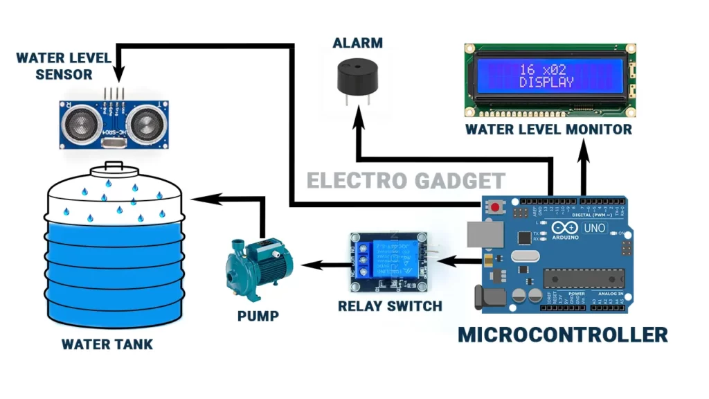
Now when the water reaches point A, input of N3 becomes high and so does the output of N4. Working of Water Level Indicator System The main function of this project is to detect and alert the system for the particular water tank level. I created the circuit usi ga unna 2003 and bc547 n bc557. To overcome the water overflow problem, there must be an alarm system to save the water wastage. The resultant collector output triggers the LED to glow showing the current level of the water in the vessel. And can i connect any S-R latch with this circuit coz it is high frequency AC.

Next