Friction loss along a pipe. FRICTION LOSS ALONG THE blog.sigma-systems.com 2022-12-21

Friction loss along a pipe Rating: 8,2/10 1606 reviews

Friction loss along a pipe is a phenomenon that occurs when a fluid, such as water or gas, flows through a pipe and encounters resistance due to the roughness of the pipe wall and the viscous nature of the fluid. This resistance causes the fluid to slow down and lose energy, resulting in a reduction in pressure and a corresponding decrease in the flow rate of the fluid. Understanding friction loss along a pipe is important in many applications, including the design of piping systems for the transportation of fluids and the calculation of pressure drop in fluid flow systems.

There are several factors that can influence the amount of friction loss along a pipe. One of the most important factors is the roughness of the pipe wall, which can vary significantly depending on the material and surface finish of the pipe. For example, a pipe with a smooth, polished surface will have less friction loss than a pipe with a rough, corroded surface. The diameter of the pipe also plays a role in friction loss, with smaller diameter pipes generally experiencing higher levels of friction loss than larger diameter pipes due to the increased surface area of the pipe wall that the fluid comes into contact with.

The viscosity of the fluid is another factor that can affect friction loss along a pipe. Viscosity is a measure of the resistance of a fluid to flow, and fluids with higher viscosities will generally experience more friction loss than fluids with lower viscosities. For example, water, which has a relatively low viscosity, will experience less friction loss than oil, which has a much higher viscosity. The temperature of the fluid can also affect viscosity, with warmer fluids typically having lower viscosities and experiencing less friction loss than colder fluids.

The flow rate of the fluid is also an important factor in determining the amount of friction loss along a pipe. In general, higher flow rates will result in higher levels of friction loss, as the fluid is moving more quickly and coming into contact with more of the roughness on the pipe wall. Similarly, the length of the pipe can also affect friction loss, with longer pipes generally experiencing higher levels of friction loss due to the increased distance that the fluid must travel and the corresponding increase in the number of opportunities for the fluid to encounter resistance.

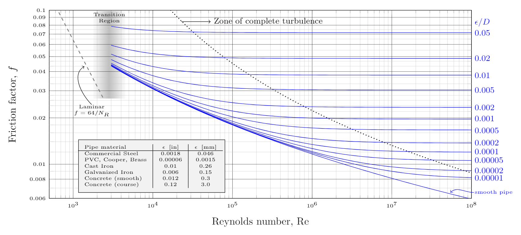
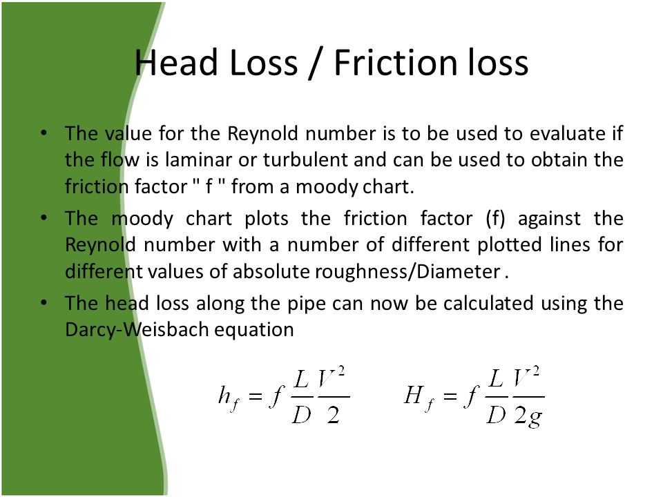
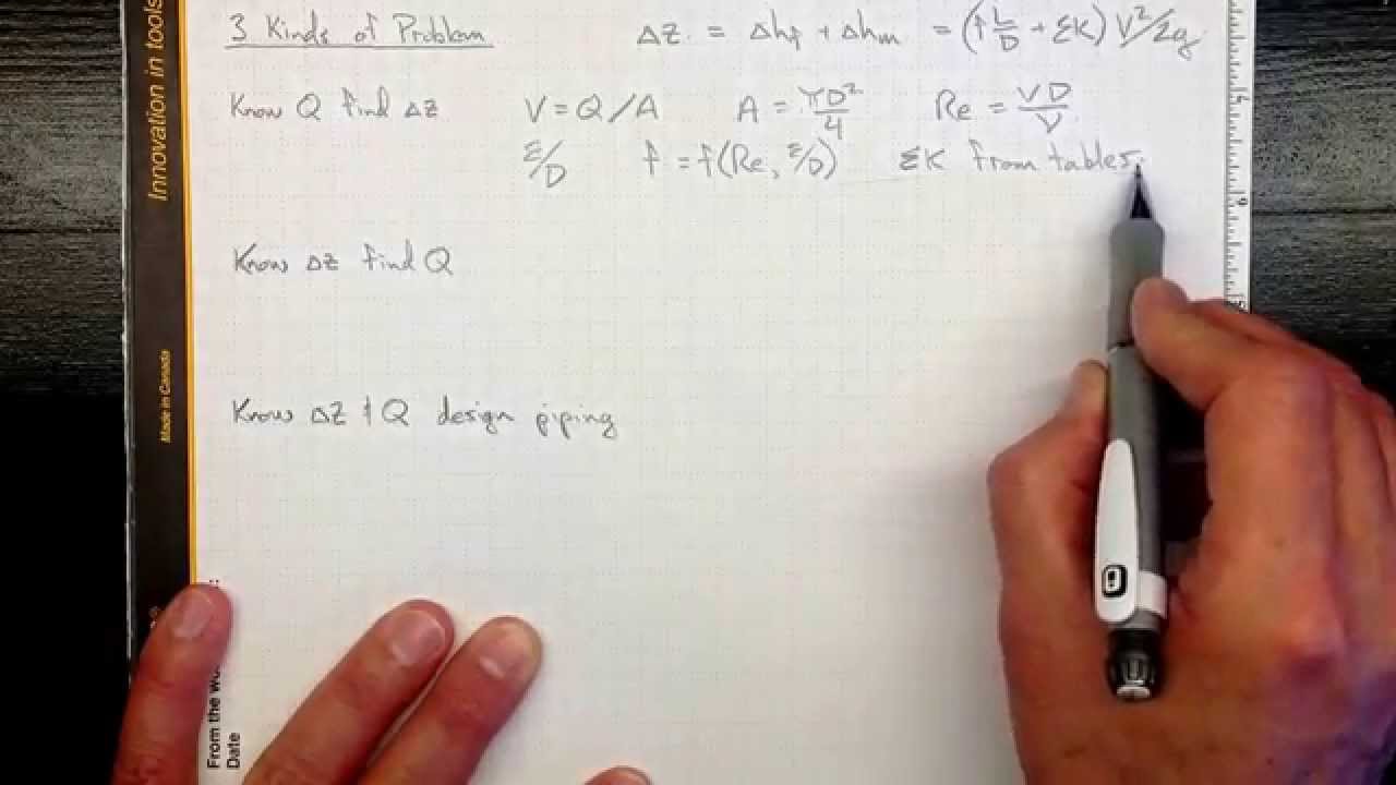
There are several methods that can be used to calculate the amount of friction loss along a pipe, including the Darcy-Weisbach equation and the Hazen-Williams equation. These equations take into account factors such as the roughness of the pipe wall, the viscosity of the fluid, the flow rate, and the diameter of the pipe to determine the pressure drop that will occur along the length of the pipe.

In conclusion, friction loss along a pipe is a phenomenon that occurs when a fluid flows through a pipe and encounters resistance due to the roughness of the pipe wall and the viscous nature of the fluid. Understanding friction loss is important in the design of piping systems and the calculation of pressure drop in fluid flow systems, and several factors, including the roughness of the pipe wall, the viscosity of the fluid, the flow rate, and the length of the pipe, can influence the amount of friction loss that occurs.

Friction Loss Along a blog.sigma-systems.com

friction loss along a pipe

Sabersky, Allan J Acosta, Edward G. Different flow rates were introduced along with a different diameters and roughness of the pipes. The Reynolds number can be defined as follows. Weisbach first proposed the relationship that we now know as the Darcy-Weisbach equation or the Darcy-Weisbach formula, for calculating friction loss in a pipe. To conclude, we chiefly studied the head losses in the pipes as along pipes of different diameters and roughness. REFERENCES A Rolf H.

Next

Experiment 1_Friction loss along a pipe lab report. blog.sigma-systems.com

friction loss along a pipe

The experiment is conducted where the head loss in the system is manipulated in order increase and decrease the velocity of the water flowing through the system. Basic Principles: The loss of energy in pipes was a mystery thoroughly investigated by Osborne Reynolds in 1883. The plan going forward is to either start some Excel course or start writing articles related to Naval Architecture. The flow rate along the tube is regulated by a valve at the outlet of the tube. In this lab the difference in height of water between two piezometers represent the total energy loss in the pipe. The Flow rate was changed to a range of different values and hence the respective values of H1 and H2 were recorded.

Next

FRICTION LOSS ALONG THE blog.sigma-systems.com

friction loss along a pipe

Throughout lab, the law of friction loss and the Venturi effect were experienced. Besides, the graph between head loss versus velocity was drawn to identify the laminar, transition and turbulent zones and a graph between log h1-h2 versus log V was used to determine the relationship between these two parameters. The head loss due to friction may be incurred by fluid when fluid experiences bends, valves, sudden expansion as well as sudden contraction at fitting. The disadvantage is that the procedure is only valid for water, at room temperature and at conventional flow velocities. The fractional factor is defined as f and symbol l is the length of pipe.

Next

Experiment 1

friction loss along a pipe

This is done by calculating the Reynolds number. As the frictional factor increased the Reynolds number decreased, this shows the inverse proportion between the friction factor f and the Reynolds number. Table 3 - Pipe roughness coefficient to be used together with Hazen-Williams Equation Material C Factor low C Factor high Cast iron new 130 130 Cast iron 10 years 107 113 Cast iron 20 years 89 100 Cast iron 30 years 75 90 Cast iron 40 years 64 83 Cement-Mortar Lined Ductile Iron Pipe 140 140 Concrete 100 140 Copper 130 140 Steel 90 110 Galvanized iron 120 120 Polyethylene 140 140 Polyvinyl chloride PVC 150 150 Fibre-reinforced plastic FRP 150 150 Friction loss in fittings, valves, equipment etc. Turbulent flows and laminar flows do not have the same resistances as each other, and so both types of flows must be studied in order to have an accurate understanding of each type of flow and how it reacts when faced with resistance. Based on our results, the maximum fractional factor is 0.

Next

Friction Loss Along a blog.sigma-systems.com

friction loss along a pipe

Another physical law examined during this experiment was the Venturi effect. We examined the flow resistance in a long, straight pipe with smooth walls in the experiment mentioned above. The results also find that the floe is laminar up to Re of 1500 and turbulent flow when higher than Re of 3500. . With these errors taken into consideration, the experimental results would be better. This resistance is termed pipe friction and is usually measured in feet or metres head of the fluid, which is why it is also refered to as the head loss due to pipe friction.

Next

Friction Losses Along a Pipe (1).pdf

friction loss along a pipe

This principle can be applied to manometers, which use this notion to measure the change in pressure between two points of a fluid flow. However the Hazen-Williams results rely upon the value of the friction factor, C hw, which is used in the formula, and the C value can vary significantly, from around 80 up to 130 and higher, depending on the pipe material, pipe size and the fluid velocity. In the other hand, the lowest percentage error and highest percentage error between calculated and measured frictional loss that obtained was 3. The article will describe how to calculate friction loss in straight pipes and fittings including examples at the end. Some of the steps are to make the flow rate of the water source consistent and remove the bubble from the tubes in the measurements. The critical Reynold number for the experiment was found to be 2517 and when compared to literature review, the deviation was found to be 9. Another possibility is to calculate the friction coefficient using the equations in the next section.

Next

Friction Loss Along a Pipe (2) (1).pdf

friction loss along a pipe

V Giles, Fluid Mechanics and Hydraulics Third Edition , McGrawHill Inc; 1994. Hydraulic diameter The purpose of the hydraulic diameter is to make it possible to use the same equations regardless of pipe shape. This consistent distances upstream and downstream of the test segment should ensure that no noise at the input or in the output of the pipe affects the performance. This condition is considered as fractional resistance is formed. The friction loss for each bend is:. The flow factor uses SI-units and is used throughout the world whereas the Flow Coefficient uses imperial units and is mainly used in the United States. When the pipe is narrow with multiple fittings, the biggest part of the lack of head is caused by the local fitting.

Next

Pipe Friction Loss Calculations

friction loss along a pipe

It show the Darcy-Weisbach friction factor as function of roughness and Reynolds number and is a quick way to quickly determine the friction factor. The only difference being the units used. It can be described as the simultaneous drop in fluid pressure as the fluid moves through the constricted section of the pipe. Therefore we measured the friction factor of the pipes using our measurements. Figure 1 is shown to clarify the difference in levels between piezometers A and B, h is definitely same with the frictional loss along a horizontal pipe with length, l. The effects of an increase and decrease in velocity needs to be considered as it is a crucial factor in determining the type of flow within a pipe, whether it be laminar, turbulent, or transitional.

Next

The Engineering Handbook

friction loss along a pipe

Aim To investigate friction loss in a small bore horizontal pipe over a range of flow rates and to carry out a risk assessment of a practical laboratory session. As the flow rate, Q was changed, the values for the inlet and outlet, H1 and H2 were measured. BAHAGIAN A LABORATORY REPORT FLUID MECHANICS LABORATORY SKPU 1711 MUHAMMAD KHAIRIL IKRAM A13KP0047 AKMAL FAIZ BIN ABDUL RAHIM A13KP0008 ABDUL WAHAB A13KP4006 KSATRIYA ANANTAYUTYA A13KP4001 Report summary: The experiment was undertaken to measure the head lost in the pipe due to shear stress between the fluid and the wall of the pipe. This resistance can be minimized but it cannot be completely eliminated, therefore it is crucial to understand how the resistance affects the movement of the fluid. It has the advantage that the factor C is independent of the Reynolds Number and consequently the cumbersome procedure of determining the friction coefficient is avoided. The first approach will be described here.

Next

FRICTION LOSS ALONG A blog.sigma-systems.com

friction loss along a pipe

Hazen-Williams Formula Before the advent of personal computers the Hazen-Williams formula was extremely popular with piping engineers because of its relatively simple calculation properties. It is defined as the 4 times the cross sectional area A divided by the perimeter P. The friction loss results are only valid for fluids with a kinematic viscosity of 1. At higher velocities, the filament, after passing a little way along the tube, suddenly mixed with the surrounding water, indicating that the motion had now become turbulent. The experiment concludes that an increase in head loss in the pipe will also increase the Reynolds number and decrease the friction force factor of the flow in the pipe. The relationship between each type of flow and the resistance it faces must be understood adequately in order to properly have fluids travelling through pipes. Whenever a fluid flow through a pipe, there will be some friction losses.


Next