How to use multisim. How do you use the spectrum analyzer? 2022-12-14

How to use multisim Rating: 9,7/10 1068 reviews

Multisim is a powerful simulation tool that allows engineers and students to design and test electronic circuits virtually. It is a part of the National Instruments Circuit Design Suite, which provides a comprehensive set of tools for circuit design, simulation, and prototyping. In this essay, we will learn how to use Multisim to design and simulate electronic circuits.

Before we begin, it is important to note that Multisim requires a computer with a compatible operating system (Windows or macOS) and a valid license to use. Once you have installed the software and activated your license, you can launch the application and begin using it.

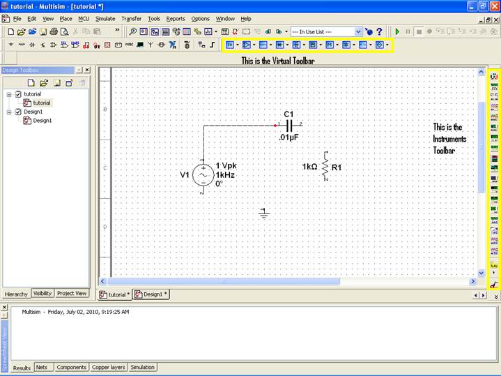
To start using Multisim, the first step is to create a new project. You can do this by clicking on the "File" menu and selecting "New" from the drop-down menu. This will open a new window where you can enter the name and location of your project. You can also choose the type of project you want to create (e.g. DC analysis, AC analysis, etc.).

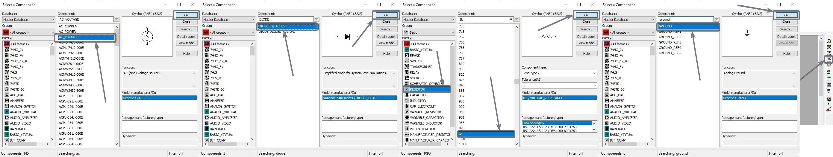
Once you have created a new project, you can start adding components to your circuit. You can do this by clicking on the "Components" tab in the toolbar and selecting the component you want to add from the list. You can also search for specific components using the search bar. Once you have selected a component, you can place it in the workspace by clicking and dragging it onto the canvas.

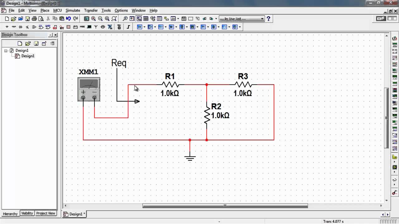
To connect the components in your circuit, you can use wires. You can add a wire by clicking on the "Wires" tab in the toolbar and selecting the type of wire you want to use (e.g. solid, dashed, etc.). You can then click and drag the wire to connect the components in your circuit.

Once you have added all the components and connected them with wires, you can simulate your circuit. To do this, click on the "Simulate" tab in the toolbar and select the type of simulation you want to run (e.g. DC analysis, AC analysis, etc.). This will open a new window with various options and parameters that you can adjust according to your needs.

After you have set the simulation parameters, you can start the simulation by clicking on the "Run" button. This will execute the simulation and generate a report with the results. You can view the results by clicking on the "Results" tab in the toolbar. The results will be displayed in the form of graphs, tables, and other visualizations, which can help you analyze and understand the behavior of your circuit.

In conclusion, Multisim is a powerful tool that allows you to design and simulate electronic circuits virtually. By following the steps outlined above, you can use Multisim to create and test your own circuits and get a better understanding of how they work.

How do you use the spectrum analyzer?

how to use multisim

Navigate to the Multisim directory as noted above and overwrite the existing two Basys 3 files. Some of these devices are even digital versions of their real-world counterparts, like the Tektronix TDS 2024, which can cost several thousand dollars. Changes made here will save permanently when you save the file. You can repeat the same with other elements in the circuit, as well. Apple iOS devices, both mobile and laptop, were checked as well with no issues. Values can be edited at any time, even while a simulation is running.

Next

frequency measurement using multisim

how to use multisim

I used the "Browser Download" option without a physical optical drive in my machine and it worked perfectly fine. The On-page Connector window will open again. Part C: Simulating the Circuit You are now ready to run an interactive Multisim simulation; however, you need a way to visualize the data. Also, all components must include footprint information. Be sure to move LabVIEW 2016 before you try and open it to avoid any possible issues.


Next

Multisim: Why, Oh Why, Would I Need That?

how to use multisim

Note that while you can change the connector labels, it is not recommended. Metric prefixes or their one-letter abbreviations can be typed in the box along with the number. Plus, there's one other thing. After placing the oscilloscope and wiring it to the input and output terminals it should look like without the yellow circle : Notice that when two wires simply pass over each other there is no connection inside the yellow circle but where the wires are actually connected the connection is represented by a dot. Here is my Basys 3 with the Full Adder circuit loaded. Therefore, both techniques are important. This is especially useful if you are trying to model real components that you have measured.

Next

How to Purchase and Activate Multisim Student Edition

how to use multisim

If you have any problems with this process, feel free to post your questions here, but a much better place would be the As you can see, programming FPGAs is really simple with Multisim. Multisim is also paired with Ultiboard, a PCB design program. Simulation is a kind of a virtual arrangement where you can have an idea of how a system will function when it is implemented in real life. Name the On-page connector —V. For a quick mobile platform view, continue on to the next step.

Next

Tutorial

how to use multisim

Selecting the operational amplifier. We have a circuit designed, built, and tested. Hi yyao, I've found ---------------- begin paste ------------- Spectrum Analyzer Spectrum Analyzer The Spectrum Analyzer is capable of measuring a signal's power and frequency components, and helps determine the existence of harmonics in the signal. You only need a working knowledge of how logic circuits work. Expand the tree that is labeled "Spectrum Analyzer".


Next

Multisim

how to use multisim

Ultiboard will create a default board outline. One file has a. In addition, there are 20+ simulated measurement devices, like a voltmeter or logic converter. Step 7: I will recommend you to use the shortcut key combination as it will be handy, and adding electronic components is something that you will need every time on Multisim. The Corporate Database is where you can save custom components to be shared with colleagues. A half-wave rectifier is the most rudimentary circuit to convert AC or alternating current to DC or direct current. Refer to the The Spectrum Analyzer is used to measure amplitude versus frequency.

Next

How to Use Multisim Live : 6 Steps

how to use multisim

Yes, life seems frustrating at times! Do you have any questions? Also, please check out the Digilent blog where I contribute from time to time. Clicking on will take you right back to the circuit editor. You can later edit your profile if you need to. From our smartphones to the computer that we use, and every other electronic gadget to accomplish a lot of small tasks, there is one thing in common. After placing the component, the Select a Component window will open again automatically. Step 8: Just type in the element that you need, in the search box, and add the appropriate element to your circuit. These values can all be edited at any time.


Next

Introduction to Multisim: Learn to Capture, Simulate, and Layout in Less Than 30 Minutes

how to use multisim

The Basys 3 configuration files that are packaged with Multisim when you install it are missing some definitions. For this exercise you will place traces on both the Copper Top and Copper Bottom layers. Multisim uses configuration files to communicate between Multisim and Vivado. If you are reading this article, you might already know about what simulation is all about, but let me explain it in one line. Part A: Selecting Components Begin by drawing your schematic in the Multisim environment.

Next

How to Download and Install NI Multisim

how to use multisim

Click and then connect the wire to wherever you need it. Follow the onscreen prompts to complete the install. For this project we'll be using basic logic gates, so select that from the menu on the left and highlight the first gate you want to place. One thing that I always find is that, the default settings for vertical range is too large for many real life RF signals. You can also click on at the top right and then make sure the tab is selected. Here is a quick video I made using my Android phone.


Next

Multisim Tutorial

how to use multisim

Components placed on the workspace area. The IN terminal of the Bode Plotter should be the stimulus INPUT and the OUT should be the RESPONSE OUTPUT. One lets you choose which collection your are currently viewing. It is a good practice to replace power sources and ground with connectors. .

Next