Multisim program. NI Multisim 2023-01-01

Multisim program Rating: 5,4/10 1371 reviews

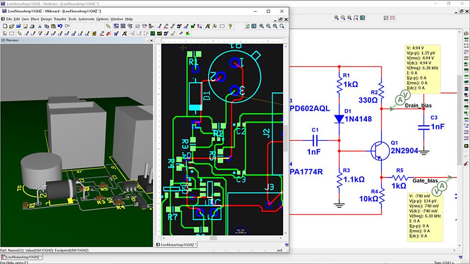
Multisim is a computer-aided design (CAD) software program that is commonly used in the field of electrical engineering. It allows users to design, analyze, and simulate electronic circuits and systems. Multisim is developed by National Instruments and is a part of the NI Circuit Design Suite, which also includes other programs such as NI Ultiboard for PCB layout and design.

One of the key features of Multisim is its ability to simulate circuit behavior. This allows users to see how a circuit will behave under different conditions and make predictions about its performance. This can be a valuable tool for identifying potential problems and debugging circuits before they are built in the real world.

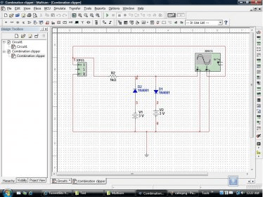
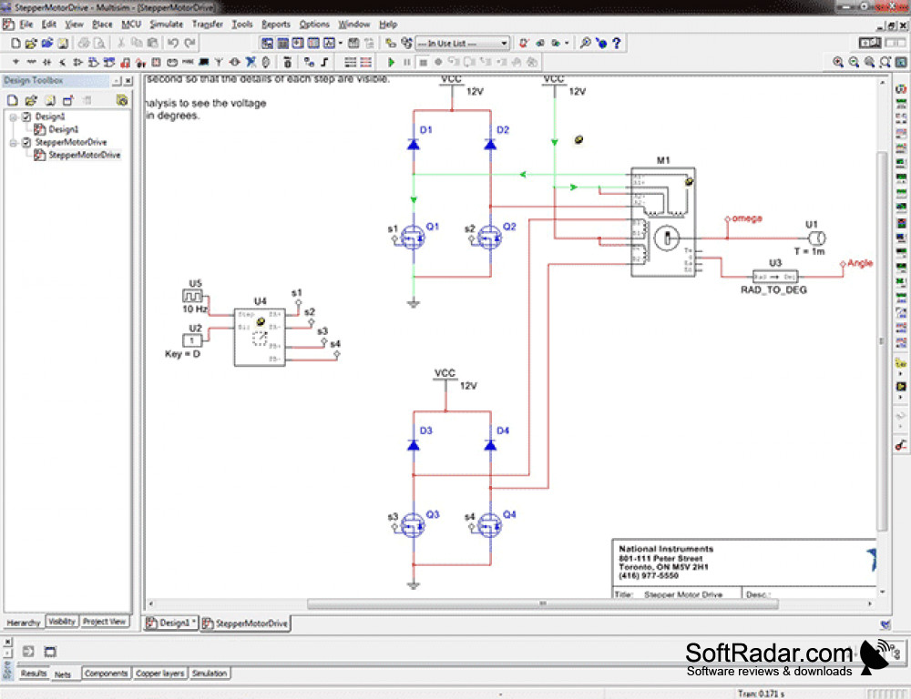
In addition to simulation, Multisim also includes a wide range of tools for designing and analyzing circuits. These include tools for drawing and editing circuit diagrams, as well as tools for performing various types of analysis, such as DC and AC analysis, transient analysis, and noise analysis.

Multisim also has a comprehensive library of electronic components that can be used in circuit design, including resistors, capacitors, inductors, and a variety of active components such as transistors and op-amps. Users can easily add these components to their designs and connect them together using virtual wires.

One of the benefits of using Multisim is that it is a user-friendly program that is easy to learn and use, even for those who are new to electronic circuit design. It has a clear and intuitive interface, with a wide range of tutorials and documentation available to help users get started.

Overall, Multisim is an essential tool for electrical engineers and other professionals working in the field of electronic circuit design. Its powerful simulation and design capabilities, as well as its user-friendly interface, make it a valuable tool for anyone looking to design and analyze electronic circuits and systems.

Programming Digilent FPGAs Using NI Multisim : 6 Steps

multisim program

I also don't recommend you modify the files unless you are confident in your abilities. Figure 1: Select Resistor Figure 2: Select DC voltage Virtual Components Components can also be placed on the circuit using virtual components. Rotate components with Ctrl+R flip them with Alt+X and Alt+Y. The Layers tab of the Design Toolbox allows you to move between layers of your design and control the appearance of the layers. Commonly, this program's installer has the following filenames: multisim.

Next

NI Multisim Student Edition 14.3

multisim program

Multisim uses configuration files to communicate between Multisim and Vivado. Demos are usually not time-limited like Trial software but the functionality is limited. Yes, download it now. With the latest release of Multisim and Ultiboard 11. This is especially useful if you want to program microcontrollers using ASM or C methods.

Next

Multisim (free version) download for PC

multisim program

Follow these steps to resize the board outline. You need to edit the actual text in the file that Multisim reads to load the correct board configuration. You can also see the phase change caused by the circuit if you click on phase button. And with Multisim, this is all that is needed to program the board. You certainly don't need to go through the struggle of learning a completely new HDL programming language. Once the install is complete, be sure to restart your computer.

Next

Programming Digilent FPGA Boards Through Multisim

multisim program

Open Multisim and start a new PLD. Note that this component is a multisection component, as shown by the A and B tabs. Should you download it? Inputs are normally on the left, while outputs are normally on the right. The new wiring might look like: I have pulled the oscilloscope a little to the right to make room for our next task Run the simulation and double click on the oscilloscope again change the divisions to the one shown below to get a similar graph. You can either select the correct valued capacitor from the list or place one and double-click it and modify the value.

Next

How to Simulate a Microcontroller in Multisim

multisim program

Find the two files labeled "DigilentBasys3". Inputs are normally on the left, while outputs are normally on the right. For this project we'll be using basic logic gates, so select that from the menu on the left and highlight the first gate you want to place. To find them, first make sure that Multisim is not running, then navigate to the root directory for Multisim. In the event something doesn't work, you can reload the original version and try again.


Next

Multisim Tutorial

multisim program

You'll see the following. Click "Next" once you're done. Copyright 2022 Designtechnica Corporation. Well, more like draw a picture, but you get the idea. NI Multisim is a perfict fit for electronic engineers and technicians alike. As expected, the input signal is being amplified by a factor of 2. My company is working with the NI software and is planning to start dabbling in FPGA's.


Next

Pricing

multisim program

Choose an appropriate spot and click to place the component. In contrast, structural design is an explicit description of the exact logic required to process the input data correctly. This means that Multisim determines the functionality of the mouse pointer by the position of the mouse. The S and Cout bits are assigned to the respective bits in 'sum'. The "Mode" determines whether the pin is defined as an input "in" , output "out" , or bidirectional pin "bidir". The Master Database contains all shipping components in a read-only format. Open Multisim and program a project to your Nexys 4 DDR as outlined in the previous steps.

Next

Introduction to Multisim: Learn to Capture, Simulate, and Layout in Less Than 30 Minutes

multisim program

Multisim lies within Education Tools, more precisely Teaching Tools. Then download The Basys 3 configuration files that are packaged with Multisim when you install it are missing some definitions. Use an intuitive environment to encourage student discovery with interactive circuit simulation and 3D prototyping. The schematic will look like the next figure: Figure 11. Since I'll be building a full adder, that seems appropriate here. After placing the oscilloscope and wiring it to the input and output terminals it should look like without the yellow circle : Notice that when two wires simply pass over each other there is no connection inside the yellow circle but where the wires are actually connected the connection is represented by a dot.

Next

Multisim Examples: Quick Functionality Overview Part I

multisim program

The initial set-up and configuration of the virtual MCU is a brief, stepwise process that can be easily accomplished. You can choose a standard definition from the drop menu, you can load a custom configuration file if you have one, or you can create an empty PLD project. Click on "Next" and then enter one of the serial numbers that came with your install materials. Get some popcorn while you watch the progress bar. If you simply want to download the correct versions and overwrite the existing files, download the DigilentBasys3. Instruments can be found on the right menu bar and are indicated by the following icons. Note that the color of the trace is red, which is the color configured for the Copper Bottom layer.


Next

NI Multisim

multisim program

Programming the FPGA The next step is to send the code to the FPGA. NI Multisim integrates industry-standard SPICE simulation with an interactive schematic environment to instantly visualize and analyze electronic circuit behavior. First, read and accept the license agreements. The ground is one of the most important components in every Multisim circuit: the mathematics of SPICE requires every circuit have a power source and a ground, or else nothing will work! You have four choices; for most circuits the generic 2-channel oscilloscope does the job. Double-click the oscilloscope and set the horizontal and vertical scales appropriately. Part E: Routing the Board Place components inside the board.

Next