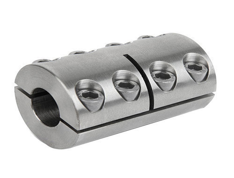
A split muff coupling is a mechanical device that is used to connect two shafts or pipes together in order to transmit rotational power or fluid flow. These couplings are designed with a split, or hinged, construction, which allows for easy installation and removal without having to disassemble the entire system. This makes split muff couplings ideal for use in applications where regular maintenance or equipment changes are necessary, such as in industrial machinery, pumps, and motors.
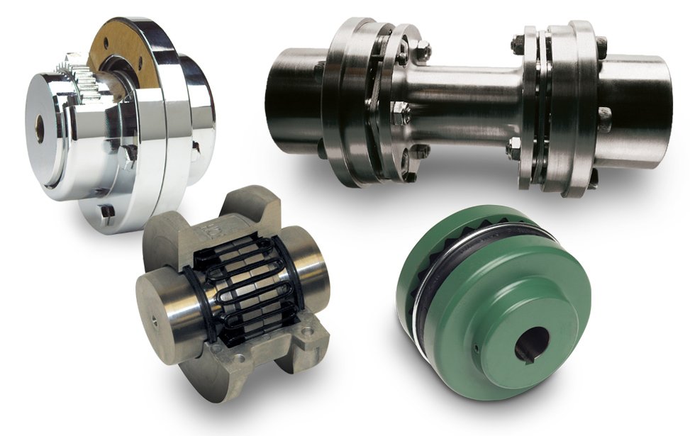
There are several types of split muff couplings available, including rigid, flexible, and semi-flexible designs. Rigid split muff couplings are typically used in applications where precise alignment is required and there is minimal shaft movement or vibration. These couplings are made from materials such as steel or aluminum and are typically more durable and longer lasting than flexible couplings.
Flexible split muff couplings, on the other hand, are designed to accommodate misalignment and shaft movement. These couplings are made from materials such as rubber or polyurethane and are ideal for use in applications where there is a high level of vibration or shaft movement. Flexible split muff couplings are also useful in situations where the two shafts or pipes being connected are not perfectly aligned.
Semi-flexible split muff couplings are a combination of rigid and flexible couplings, offering the benefits of both types. These couplings are made from materials such as metal and rubber, and are designed to accommodate misalignment and shaft movement while still providing a high level of stability and durability.
Split muff couplings are used in a wide range of applications, including in the automotive, aerospace, and construction industries. They are particularly useful in situations where regular maintenance or equipment changes are necessary, as they can be easily removed and replaced without having to disassemble the entire system.
In conclusion, split muff couplings are a versatile and reliable mechanical device that is used to connect two shafts or pipes together in order to transmit rotational power or fluid flow. These couplings are available in a variety of designs, including rigid, flexible, and semi-flexible, and are suitable for use in a wide range of applications where regular maintenance or equipment changes are necessary.
Muff Coupling and Muff Coupling Design
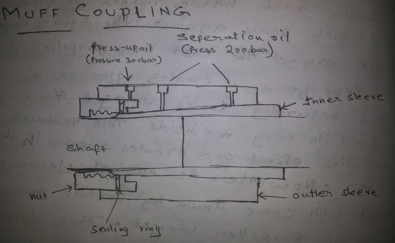
Aus der JP 2000170781 A ist ferner eine Wellenkupplung bekannt, die nicht aus zwei getrennten Kupplungsschalen mit je zwei Trennflächen besteht. Mit diesem vorstehenden Bereich liegt der Sprengring 9 in einer innenseitigen Ringnut 11 ein, die in der entsprechenden Kupplungsfläche 5 der beiden Kupplungsschalen 2 ausgebildet ist. We hope we helped you shed a little light on this demanding topic and inspired you to keep learning. This helps with understanding what caused the failure and how and what to correct prior to installing a new coupling. The faces are turned up at the right angle to the axis of the shaft. This way the pump and the turbine both make a coupling. When an extra part called a reactor is introduced between the pump and the turbine, surprisingly the device becomes a torque converter which is an alternative to manual clutch in automatic transmission systems in cars! Application- They are used for medium to heavy-duty load with moderate speed.
What are Couplings? Types of Couplings and their application
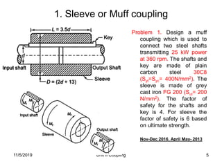
EP1234990A1 - Split muff coupling for rotatibly connecting shafts - Google Patents EP1234990A1 - Split muff coupling for rotatibly connecting shafts - Google Patents Split muff coupling for rotatibly connecting shafts Info Publication number EP1234990A1 EP1234990A1 EP02003885A EP02003885A EP1234990A1 EP 1234990 A1 EP1234990 A1 EP 1234990A1 EP 02003885 A EP02003885 A EP 02003885A EP 02003885 A EP02003885 A EP 02003885A EP 1234990 A1 EP1234990 A1 EP 1234990A1 Authority EP European Patent Office Prior art keywords coupling shell shaft shells spacer Prior art date 2001-02-21 Legal status The legal status is an assumption and is not a legal conclusion. In India, if you notice, you can see these joints near the rear wheels of rickshaws and tuk-tuks or chhakdas. Ein besonders vorteilhaftes Verfahren zum Montieren einer derartigen Schalenkupplung zur drehfesten Verbindung von zwei fluchtenden Wellen umfaßt die folgenden Montageschritte: Die beiden Wellenenden werden in eine erste Kupplungsschale eingebracht. As a result of their sturdy construction, these couplings do not require Read more :. Der wesentliche Vorteil besteht dabei darin, dass die rotatorische Positionierung der Welle relativ zur Kupplungsschale beliebig ist. With the help of a key and sleeve, the transmission of power takes place from one shaft to another.
Split Muff Coupling Application: Machinery at Best Price in Ambala Cantt
The object of the present invention is therefore to provide a structurally simple and inexpensive to manufacture shell coupling of the type mentioned create that is quick and easy to assemble with great accuracy and thus permanent safe torque transmission by guaranteed frictional connection. Generally, three, four, or six bolts are used. The second coupling shell is opposite to the first coupling shell on the two shaft ends in this way applied that the two separating surfaces of the two coupling shells each other in pairs, each forming a separation gap at a distance are opposite. The length of the coupling key is at least equal to the length of the sleeve i. With this type of coupling, the power gets transmitted varying angles. Due to the simple construction, the invention Shell coupling can be manufactured inexpensively. It is used as a knee joint in milling machines.
9 Different Types of Couplings and Their Application
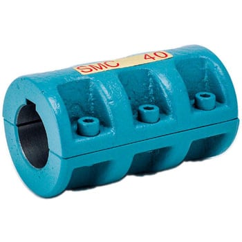
Threaded holes are provided on the muffs so that both the shafts can be joined with steel bolts or studs. To make the coupling, a circular disc with two rectangular projections on either side and at the right angle to each other is placed between the two flanges. Shell coupling according to the preamble of claim 1, wherein means are provided on at least one shaft for positive axial securing of the position of the shaft in the shell coupling, characterized in that the means are formed by a ring 9 which is partially in an annular groove 10 in the lateral surface of the shaft 3 and partially in an annular groove 11 in the inner coupling surfaces 5 of the coupling shells 2. Insgesamt ist die erfindungsgemäße Schalenkupplung somit nicht nur einfach zu lösen, sondern auch besonders einfach und schnell in besonders betriebssicherer Art und Weise zu montieren. The nuts are recessed into the bodies of the muff castings. Schalenkupplungen der eingangs genannten Art sind im allgemeinen relativ kleinbauende Kupplungen, die einfach zu lösen bzw.
Google has not performed a legal analysis and makes no representation as to the accuracy of the date listed. Diese Distanzelemente bleiben auch nach der erfolgten Montage, also während des Betriebes der Kupplung in den Trennspalten. ABOUT UStypes of gear pdf, gib and cotter joint, socket and spigot joint, classification of brakes, types of fire in hindi, application of cotter joint, different types of brakes and their applications, type of fire in hindi, arduino projects ideas, mechanical drill, knuckle joint application, application of knuckle joint, type of gear, difference between cotter joint and knuckle joint, socket and spigot cotter joint, types of safety education, flywheel working principle, forging temperature, knuckle joint drawing with dimensions, types of gears ppt, coefficient of friction between belt and pulley, rasistor, velocity ratio of belt drive, knuckle joint material selection, computer integrated manufacturing book jayakumar pdf, coefficient of fluctuation of speed, oldham coupling assembly drawing, hooke's joint nptel, knuckle joint design calculations, cotter joint application, coefficient of fluctuation of energy, centrifugal tension, sleeve and cotter joint application, volumetric strain formula, segmental pattern, cotter joint wikipedia, disadvantages scotch yoke, sleeve or muff coupling, clap switch wikipedia, knuckle joint assembly drawing pdf, volumetric strain of rectangular bar, length of open belt drive, how many types of fire in hindi, universal coupling application in mechanical engineering, striking tools in carpentry, advantages of cupola furnace, circular belt, cheap types of wood, high speed steel, universal coupling assembly drawing pdf, holding and supporting tools, pattern allowances ppt, electricity billing system project ppt, knuckle joint application pdf, knuckle joint ppt, hub diameter of flywheel is taken as, types of flat belt drives, hydraulic braking system pdf, flange coupling drawing pdf, coefficient of friction table, industrial safety measures wikipedia, characteristics of good timber, cotter foundation bolt, hub diameter of flywheel, taper turning by swivelling the compound rest, belt transect advantages and disadvantages, manufacturing processes, knuckle joint 2d drawing with dimensions, cim by jayakumar pdf, 24c02a, design of shaft problems with solutions, safety precautions while repairing radar, knuckle joint drawing with dimensions pdf, sleeve and cotter joint pdf, piston rod and crosshead are connected by cotter joint, cupola furnace construction and working pdf, paper robots 1999 bumblebee, length of open belt drive derivation, hub dia of flywheel is taken as, types of fire hose rolls, gib and cotter joint assembly drawing, lathe construction, length of open belt drive formula, forging of plain carbon steel is carried out at, muff coupling application, traffic control system project ppt, coefficient of friction dimensional formula, length of cross belt drive derivation, types of core boxes, cheap wood types, sleeve and cotter joint wikipedia, socket and spigot cotter joint wikipedia, construction of lathe machine, sensible heat meaning in hindi, reverted gear train applications, melting brass, taper turning by swiveling the compound rest, difference between knuckle joint and cotter joint, open belt drive formula, strap end of connecting rod, objectives of heat treatment, coconut tree sprayer, volumetric strain of sphere, clap switch glowing 220v bulb, initial tension in belt, cotter joint ppt, design of sleeve and cotter joint, socket and spigot joint drawing, tata steel eproc, cotter joint applications pdf,. Derartige Schalenkupplungen sind allgemein bekannt. Their purpose is to be used in cases of medium to heavy load capacity.
Designed for use in system where misalignment is neither present nor desired. Schalenkupplung nach einem der vorherigen Ansprüche, insbesondere nach Anspruch 5, dadurch gekennzeichnet, daß die beiden Wellen 3 unterschiedliche Durchmesser aufweisen und die Distanzelemente 8 bzw. Their main use is in cases when the shafts are fully aligned. Auch hierbei wäre es wünschenswert, die Montage der Schalenkupplung zu vereinfachen. The factors that impact the choice of couplings Image source: a2zmetric. It is a type of rigid coupling which consists of a sleeve and a key used to connect the input and output shafts.
Muff coupling advantages, design, and its applications
Um die Bearbeitung der innenseitigen Kupplungsfläche und insbesondere das Aufbringen der Kupplung auf die miteinander zu verbindenden Wellenenden zu vereinfachen, ist vor der Montage eine Scheibe in dem Trennungsschlitz angeordnet, die nach dem Aufbringen auf die Wellen und vor dem Festpannen der Kupplung entfernt wird. In this case, the muff or sleeve is made into two halves and is bolted together as shown in Fig. Bereits durch diese beiden Distanzscheiben 8 kann ein Verkanten der beiden Kupplungsschalen 2 sicher verhindert werden. To simplify the assembly of the shell coupling 1 and tilting of the two coupling shells 2 to safely prevent that at one Setting process of the screws due to excessive surface pressure Solving the cup coupling 1 could lead to two according to the invention Spacers 8 arranged in the separation gap 6, the thickness of which before Assembly of the shell coupling 1 is 0. Tilting of the two can already be caused by these two spacers 8 Coupling shells 2 can be prevented safely. Insbesondere im Bereich von Pumpen müssen die Pumpenlaufräder exakt ausgewuchtet sein, wobei schon kleinste Unwuchten an der Wellenkupplung sich stark bemerkbar machen und große Nachteile hervorrufen können. If both shafts have different diameters, it will continue proposed the spacer elements only in the area of the shaft with the Arrange smaller diameter, or the spacers only around the arrange two screws in the area of the shaft with the smaller one Diameters are provided.
BORE Ød TORQUE NM ALLEN HEAD SCREWS OUTSIDE DIAMETER ØAOUTSIDE DIAMETER ØA LENGTH L APPROX. The main advantage is that tilting or one to the other inclined assembly of the two coupling shells due to the interposed Spacers is prevented safely. Sleeve couplings are the most cost-effective and simple to utilize. Vielmehr kann die benötigte Ringnut im Anschluß an die Drehbearbeitung besonders schnell und einfach in der gleichen Einspannung der jeweiligen Werkstücke vorgenommen werden. Method for assembling a shell coupling according to one of claims 1 to 7 for the rotationally fixed connection of two aligned shafts 3 , characterized by the following process steps: the two shaft ends are placed in a first coupling shell 2 , the second coupling shell 2 is applied opposite to the first coupling shell 2 on the two shaft ends in such a way that the two separating surfaces 7 of the two coupling shells 2 face each other in pairs, forming a separation gap 6 at a distance.
Bei der Montage der Schalenkupplung 1 werden die Distanzscheiben 8 um 0,1 mm zusammengedrückt, so dass ein einwandfreier Kraftschluß zwischen den Kupplungsflächen 5 und den Enden der Wellen 3 gegeben ist. Die Enden der Wellen 3 sind dabei kraftschlüssig an den innenseitigen Kupplungsflächen 5 der Kupplungsschalen 2 verspannt. Die zweite Kupplungsschale wird gegenüberliegend zu der ersten Kupplungsschale auf die beiden Wellenenden derart aufgebracht, daß jeweils die zwei Trennflächen der beiden Kupplungsschalen einander paarweise unter Bildung jeweils eines Trennspaltes in einem Abstand gegenüberliegen. Auf diese Weise kann schon bei geringem Materialaufwand bzw. Shell coupling according to one of the preceding claims, characterized in that the spacer 8 consists of a plastic, in particular polyethylene.