The joule thief. Make a Joule Thief : 4 Steps (with Pictures) 2022-12-30

The joule thief Rating: 8,4/10 642 reviews

The Joule thief, also known as a blocking oscillator, is a simple yet innovative electronic circuit that is used to efficiently power low-power devices such as LEDs and small motors. It is called a Joule thief because it is able to "steal" energy from weak batteries and use it to power devices that would otherwise not be able to function with such a low voltage.

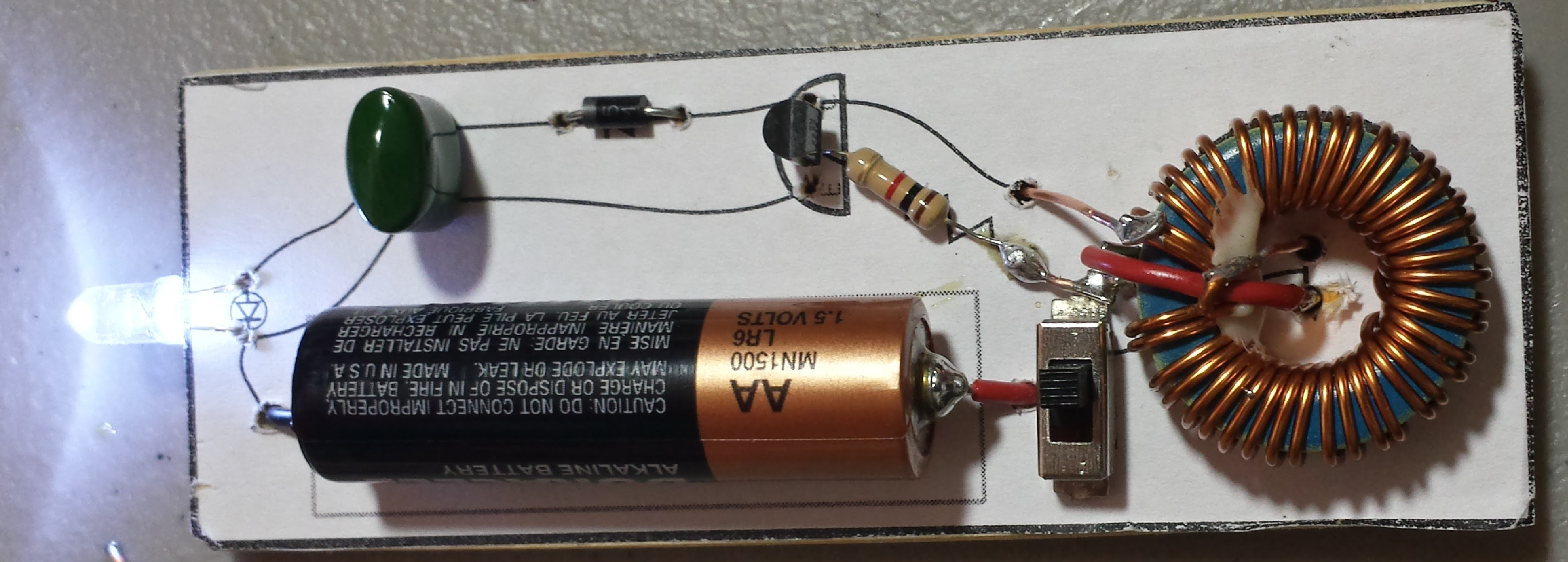
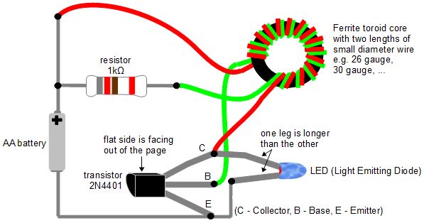
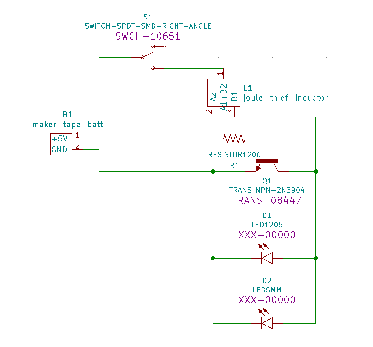
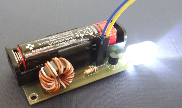
The Joule thief consists of a transformer, a transistor, and a resistor. The transformer is used to step down the voltage of the battery, while the transistor acts as a switch that turns the circuit on and off rapidly. The resistor is used to limit the current flowing through the circuit.

To understand how the Joule thief works, let's consider a simple circuit that consists of a weak battery, an LED, and a resistor. When the LED is connected directly to the battery, it may not light up because the voltage of the battery is too low. However, when the Joule thief is introduced into the circuit, the transformer steps down the voltage of the battery and the transistor rapidly switches the circuit on and off. This causes the LED to flicker at a high frequency, which is too fast for the human eye to perceive. The result is that the LED appears to be continuously lit, even though it is actually being turned on and off at a very high rate.

One of the main advantages of the Joule thief is its efficiency. Because it is able to extract energy from weak batteries and use it to power devices, it can be used to extend the life of batteries that would otherwise be discarded. Additionally, the Joule thief is very simple and can be easily built using common components, making it an affordable and accessible solution for powering low-power devices.

In conclusion, the Joule thief is a simple yet innovative electronic circuit that is used to efficiently power low-power devices. Its ability to "steal" energy from weak batteries and use it to power devices makes it an efficient and cost-effective solution for a wide range of applications.

The Joule Thief : 5 Steps

the joule thief

The only way to answer the question is to develop a business model that estimates sales rate as well as cost as well as how long you plan to sell the device. And if your custom filling your cans, we can see the Joule Thief is the lighter complete system on day one, but eventually becomes heavier as it sips its fuel each day and the toaks overtakes it or undertakes it i guess and both systems reach a constant weight on day 5 when they run out of fuel. It seems to me that normal 2-cell flashlights even a Mini Maglight would make a good home for your circuit. The results are all available in the following The resistance of R1 is inversely proportional to the input current at a given voltage. .

Next

MOSFET

the joule thief

The LED current was 20 mA so 1. Will the 5252F chip work with a single LED? When the magnetic field has fully collapsed, the negative base voltage reduces and the battery voltage starts to take over, via the resistor and when it is above 0. But I brought 2x 5 or 6 meter lengths of Stranded copper wire unknown gauge from dicksmiths electronics insulated wire, and I wound most of it on except I think a few feet left over. Recent purchases: 80 x 0. At night it easily illuminates a 25-foot hallway, using a "dead" AAA cell. Both generated using the same environmental conditions mentioned above. Swagatam, Using the same principle, I want to make a charging circuit for 12V lead batteries with 12Volt DC voltage.


Next

2013

the joule thief

If all is working well, the LED will light up! I found mine in an old computer power supply, and it works fine for me. I just repeated these tests and got much improved results now. I don't know if the circuit would work with a 2-cell battery. But that weight should be the Joule Thief + BRS 3000t + 19 gram fuel can + fuel. When all is according to my liking I'll make some more of these with red lights for use at the telescope.

Next

The "Reverse Joule Thief" Battery Charger : 6 Steps

the joule thief

Based on the following charts I chose to change the value of R1 from the original 1K to 6. But I guess specifications can vary. Joule Thief with BRS 300T vs Toaks 550ml with BRS 300T. But a physically smaller wafer capacitor would work as well. Forgive me for asking, but to whom does the SLS printer belong? For these graph, I purposely chose a trip duration of 5 days because it shows something interesting in both cases.

Next

High Efficiency Regulated Joule Thief : 4 Steps (with Pictures)

the joule thief

But the amount of power converted is directly related to the battery voltage, which changes as the battery discharges, so there has to be something to compensate for the change. A small amount of electricity goes through the resistor and the first coil to the base of the transistor. This is not a problem for a guy with a VOM. The pot is left on the centrifuge for the silicone to cure under the centrifugal force. I have a transformer 220 V to 20V, the core is about 30 mm x 30 mm x 30 mm.

Next

Red Light for Illumination

the joule thief

So I rooted through my electronics parts to find enough to make a demonstration light. The input will be 5V and I will apply it to the Gate leg of the mosfet with a 220R resistor. But for those of you who like it in text, here it is: Helping Hands Optional Soldering Iron Solder A Blue or White LED Other colors are fine, too 2N3904 Transistor or equivalent 1k Resistor Brown-Black-Red Toroid Bead Thin wire, two colors magnet wire works You can get the toroid and transistor from a dead CFL; the transistor is usually labeled 13002. At 2 milli-amps it is quite bright. A drop in the amount of electricity in the second coil induces a negative amount of electricity in the first coil. I used both ferrite core and transistor from a dead CFL and did the test with a "dead" 1.

Next

microcontroller

the joule thief

May be with the time it will drift more than the voltage generated by the previous version with the Schmitt trigger. See the diagram above. But I still give kudos on this build just the way it is. So be aware of that possibility and not leave a dead battery in its holder for a long period of time. This arrangement was chosen due to its advantages for this kind of application. The fresh battery has low internal resistance and the capacitor may have little effect.

Next

3 Best Joule Thief Circuits

the joule thief

The plot below shows that increasing the resistance of R1 causes the current passing through the LED to increase at a given input power. I'll have to remeasure it and do the test again in more detail. Another solution could be to increase the number of the turns of the coils or at least their ratio Not sure what you mean i checked to see that i was getting a voltage across my inductor. Yeah, I'm an Hp collector, too. The input will be 5VDC, and the output will be a battery that will be kept in drop charge. This causes even less electricity to go into the base of the transistor.

Next